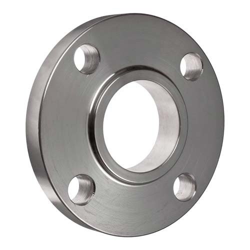
Welded connections
Slip-On Flanges
The flange bore slips over the pipe before the connection is secured with fillet welds. Pipe outside diameter and installation clearance govern the fit.


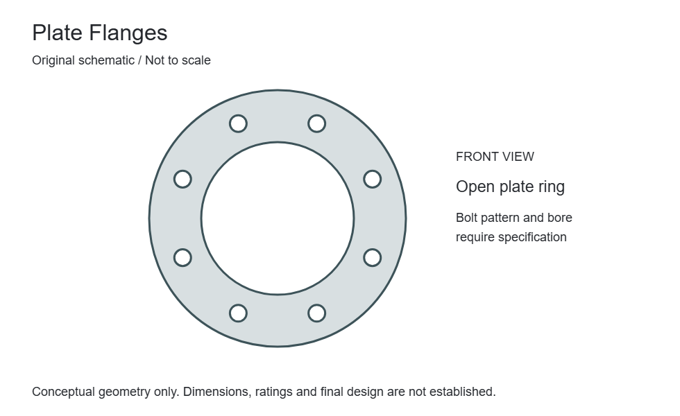
Construction & special designs
A plate flange is a ring-shaped component made from plate, with an open bore and a bolt pattern specified for the mating connection. Plate construction is distinct from a flat gasket facing.
Plate thickness, material specification and the pipe attachment determine how this construction can be used. A ring cut from plate must not inherit the ratings of a forged flange simply because its bolt holes match. State the governing design basis and intended service with the enquiry.
Compare flange typesDefine whether the ring is welded to the pipe or used in another approved assembly. The bore clearance, weld arrangement and required inspection follow that construction, rather than a generic flange name.
A plate flange may have a specified flat seating surface, but flat-face terminology alone does not identify plate material or manufacture. Confirm both the construction and the gasket-contact requirements.
Define Plate Flanges as part of the complete joint. These fields identify required engineering data; they are not universal dimensions or a declaration of available sizes.
| Parameter / designation | Technical information | Selection requirement |
|---|---|---|
| Nominal size and bore | State the nominal connection size separately from the actual bore or pipe outside diameter. | A matching size label does not establish matching internal geometry. |
| Outside diameter and thickness | Identify the finished flange diameter, minimum thickness and any hub or collar projection. | Include the drawing datum and units for replacement measurements. |
| Bolt circle and holes | Record pitch-circle diameter, hole quantity, hole diameter and any special orientation. | Check against the mating flange; do not infer a bolt pattern from pressure class alone. |
| Gasket-contact surfaces | Specify face form, seating dimensions and surface finish on the assembled joint. | Include gasket designation; a visually similar surface is not evidence of compatibility. |
| Pipe-side interface | Identify weld preparation, socket, thread, collar or other attachment geometry as applicable. | Provide pipe schedule/wall thickness and the connection-specific standard. |
| Design conditions | State design pressure, minimum/maximum temperature, fluid and mechanical loads. | Pressure class is not a pressure value in bar or psi. Use the material-specific rating basis. |
Compare Plate Flanges with the related forms or references below. A related product is not necessarily a permissible substitute.
| Related product / reference | Distinction | Check before selection |
|---|---|---|
| Slip-On Flanges | The flange bore slips over the pipe before the connection is secured with fillet welds. Pipe outside diameter and installation clearance govern the fit. | Slip-over bore with project-specified fillet welds |
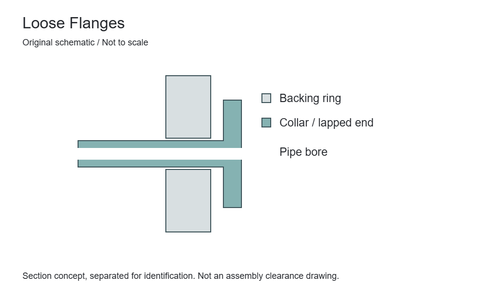
| Loose Flanges | A loose flange is a separate backing component working with a collar, lapped end or stub end. It transfers bolt load while the companion component forms the pipe-side seating interface. | Collar or stub-end designation and drawing |
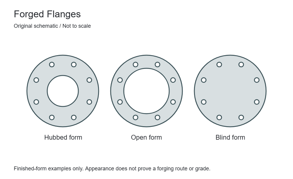
| Forged Flanges | Forged flanges describe a manufacturing route spanning several connection forms, including weld neck, slip-on and blind. The flange type must still be specified. | Weld neck, slip-on, blind or other specified form |
Define acceptance requirements for Plate Flanges in the purchase order. Required examinations and documents depend on the material, design and project specification.
| Review stage | Information to confirm | Order requirement |
|---|---|---|
| Material identity and traceability | Specification, grade, heat/lot identification and the required material certificate. | Agree documentation and marking before manufacture; visual appearance cannot verify alloy identity. |
| Dimensional verification | Critical dimensions from the selected standard or controlled drawing. | Identify inspection points, tolerances, units and drawing revision. |
| Surface and end condition | Gasket-contact surface, attachment end, edges and any coating exclusions. | State finish and visual acceptance criteria; agree protection of machined surfaces. |
| Supplementary examinations | Any specified PMI, NDE, hardness, impact, corrosion or other tests. | Define the method, sampling and acceptance criteria; tests are not automatically included. |
| Assembly compatibility | Adjoining components, weld or mechanical interface and project service conditions. | Design approval and correct assembly remain separate from a dimensional inspection report. |
| Packing and order release | Quantity, identification, surface protection, documents and delivery destination. | Agree preservation, packaging and release requirements with the order. |
Specification checklist
Availability, dimensions and pressure-temperature suitability are confirmed against your complete enquiry.
| Item | Requirement |
|---|---|
| Material | State the plate specification, grade and thickness |
| Attachment | Identify the pipe connection and weld details |
| Interface | Provide outside diameter, bore, bolt circle and hole pattern |
| Design basis | Specify the applicable standard or approved calculation and drawing |
| Material & quantity | Exact material designation, quantity and required certification or inspection documents |
Application context
Related connections
Welded connections
The flange bore slips over the pipe before the connection is secured with fillet welds. Pipe outside diameter and installation clearance govern the fit.
Mechanical connections
A loose flange is a separate backing component working with a collar, lapped end or stub end. It transfers bolt load while the companion component forms the pipe-side seating interface.
Construction & special designs
Forged flanges describe a manufacturing route spanning several connection forms, including weld neck, slip-on and blind. The flange type must still be specified.