Branch connections
Weldo Flanges
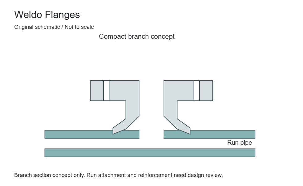
A Weldo flange combines a flanged branch connection with a weld-on outlet form at the run pipe. The branch-to-run interface is a defining part of the requirement.


Branch connections
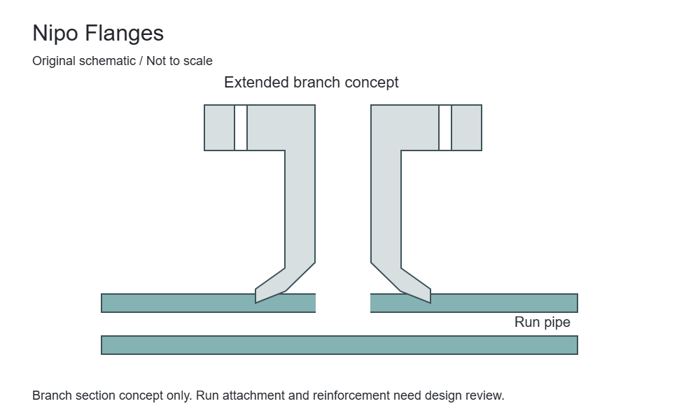
A Nipo flange is a flanged branch-outlet form with a nipple-like extended neck. Projection and the run-pipe attachment must be defined as part of the complete branch.
The extended branch can provide separation between the run pipe and the bolted interface, but its length is a design input rather than a universal catalogue dimension. Include loads, clearance and the attachment configuration. Confirm the supplier terminology against a profile drawing.
Compare flange typesDefine projection from a stated datum, such as the run-pipe surface or centreline. Account for insulation, bolt access and the connected equipment without assuming that any extended neck is acceptable.
An extended neck does not replace the run-pipe reinforcement and attachment assessment. Specify the piping code, run wall, weld detail and inspection scope together with the flanged-end standard.
Define Nipo Flanges as part of the complete joint. These fields identify required engineering data; they are not universal dimensions or a declaration of available sizes.
| Parameter / designation | Technical information | Selection requirement |
|---|---|---|
| Nominal size and bore | State the nominal connection size separately from the actual bore or pipe outside diameter. | A matching size label does not establish matching internal geometry. |
| Outside diameter and thickness | Identify the finished flange diameter, minimum thickness and any hub or collar projection. | Include the drawing datum and units for replacement measurements. |
| Bolt circle and holes | Record pitch-circle diameter, hole quantity, hole diameter and any special orientation. | Check against the mating flange; do not infer a bolt pattern from pressure class alone. |
| Gasket-contact surfaces | Specify face form, seating dimensions and surface finish on the assembled joint. | Include gasket designation; a visually similar surface is not evidence of compatibility. |
| Pipe-side interface | Identify weld preparation, socket, thread, collar or other attachment geometry as applicable. | Provide pipe schedule/wall thickness and the connection-specific standard. |
| Design conditions | State design pressure, minimum/maximum temperature, fluid and mechanical loads. | Pressure class is not a pressure value in bar or psi. Use the material-specific rating basis. |
Compare Nipo Flanges with the related forms or references below. A related product is not necessarily a permissible substitute.
| Related product / reference | Distinction | Check before selection |
|---|---|---|
| Weldo Flanges | A Weldo flange combines a flanged branch connection with a weld-on outlet form at the run pipe. The branch-to-run interface is a defining part of the requirement. | Outside diameter, schedule, material and orientation |
| Long Weld Neck Flanges | An extended neck combines a flanged connection with a longer nozzle section. Neck length, bore and end preparation must be specified for the intended equipment connection. | Provide required projection, wall and bore |
| Weld Neck Flanges | A tapered hub carries the connection from the flange body to a butt-welded pipe end. The pipe bore and wall thickness are important parts of the flange specification. | Butt-weld end; specify pipe schedule and bore |
Define acceptance requirements for Nipo Flanges in the purchase order. Required examinations and documents depend on the material, design and project specification.
| Review stage | Information to confirm | Order requirement |
|---|---|---|
| Material identity and traceability | Specification, grade, heat/lot identification and the required material certificate. | Agree documentation and marking before manufacture; visual appearance cannot verify alloy identity. |
| Dimensional verification | Critical dimensions from the selected standard or controlled drawing. | Identify inspection points, tolerances, units and drawing revision. |
| Surface and end condition | Gasket-contact surface, attachment end, edges and any coating exclusions. | State finish and visual acceptance criteria; agree protection of machined surfaces. |
| Supplementary examinations | Any specified PMI, NDE, hardness, impact, corrosion or other tests. | Define the method, sampling and acceptance criteria; tests are not automatically included. |
| Assembly compatibility | Adjoining components, weld or mechanical interface and project service conditions. | Design approval and correct assembly remain separate from a dimensional inspection report. |
| Packing and order release | Quantity, identification, surface protection, documents and delivery destination. | Agree preservation, packaging and release requirements with the order. |
Specification checklist
Availability, dimensions and pressure-temperature suitability are confirmed against your complete enquiry.
| Item | Requirement |
|---|---|
| Run interface | Pipe outside diameter, wall and attachment contour |
| Projection | Required length and measurement datum |
| Flanged end | Size, class, facing, bore and bolt pattern |
| Design conditions | Pressure, temperature, loads and branch design basis |
| Material & quantity | Exact material designation, quantity and required certification or inspection documents |
Application context
Related connections
Branch connections
A Weldo flange combines a flanged branch connection with a weld-on outlet form at the run pipe. The branch-to-run interface is a defining part of the requirement.
Welded connections
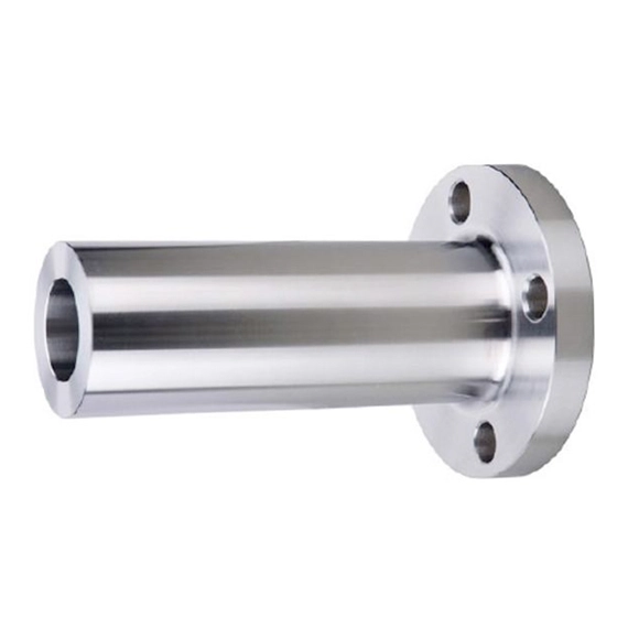
An extended neck combines a flanged connection with a longer nozzle section. Neck length, bore and end preparation must be specified for the intended equipment connection.
Welded connections
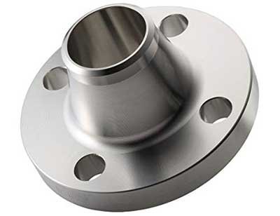
A tapered hub carries the connection from the flange body to a butt-welded pipe end. The pipe bore and wall thickness are important parts of the flange specification.